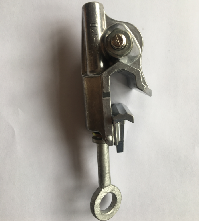
De-energizing a circuit and applying Lockout/Tagout (LOTO) protocols does not entirely eliminate the risk of fatal electrical shock during maintenance. Accidental re-energization, backfeed, switching errors, and induced voltages from adjacent live lines present persistent threats to personnel on the ground. Without adequate temporary grounding procedures, workers face severe liability and safety risks. Portable Earth Equipment serves as the mandatory fail-safe mechanism to protect personnel in these hazardous environments.
This article provides a technical evaluation guide for specifying, selecting, and implementing the correct grounding kits based on fault current ratings, site environments, and regulatory standards. Understanding how to deploy these systems correctly ensures compliance and safeguards lives during critical electrical maintenance operations.
Primary Function: Portable earth equipment acts as a critical secondary defense, creating a low-impedance short-circuit path to ground that triggers protective relays and establishes an Equipotential Zone (EPZ) for worker safety.
Specification Dependency: Selection cannot be generic; components must be strictly matched to the maximum available fault current, X/R ratio, and the clearing time of the circuit's protective devices.
Compliance is Non-Negotiable: All grounding kits and components must meet stringent industry standards (e.g., ASTM F855, IEC 61230, OSHA regulations) to ensure they survive the extreme mechanical and thermal stresses of a fault.
Maintenance & Inspection: The effectiveness of portable grounding degrades over time. Rigorous pre-use inspections and scheduled micro-ohmmeter testing are mandatory to mitigate implementation risks.
The Core Function of Portable Earth Equipment
Problem Framing (Success Criteria)
Temporary grounding is required when personnel perform maintenance on de-energized electrical systems where the potential for accidental re-energization exists. The success criterion for portable earth equipment is its ability to keep the voltage across the worker within safe limits during a fault event. This requires a robust, low-impedance path to ground capable of handling massive energy surges without failing. We evaluate these systems based on their capacity to carry maximum fault current until the upstream protective devices clear the circuit.
Field crews often encounter situations where parallel transmission lines induce dangerous voltages on the de-energized line they are working on. In these scenarios, the grounding system must continuously bleed off this induced energy while remaining ready to handle a full-scale fault. The mechanical forces generated during a short circuit are immense, often causing cables to whip violently. If the equipment is not rated for these forces, clamps can blow off the busbar, leaving workers completely unprotected.
Mitigating Accidental Energization
When accidental energization occurs, portable earth assemblies handle sudden fault currents by providing a direct path to ground. This massive current flow forces upstream breakers or fuses to clear the circuit rapidly. The equipment must withstand the thermal and mechanical forces of the fault until the protective devices operate, preventing lethal voltage levels from reaching the worker. The physics of a fault event dictate that the grounding cable will heat up rapidly, and the magnetic forces will attempt to tear the assembly apart.
To mitigate these risks, engineers must calculate the available fault current at the specific work location. This calculation determines the required cross-sectional area of the grounding cable and the mechanical strength of the clamps. A common mistake in the field is assuming that a standard grounding set is sufficient for all locations. In reality, a set designed for a distribution line will likely vaporize if applied to a high-capacity transmission substation bus.
Three-Phase Short-Circuiting vs. Single-Phase Grounding Configurations
Multi-phase "spider" kits short-circuit all phases together before connecting to ground. This configuration ensures that any fault immediately becomes a multi-phase fault, drawing maximum current and triggering protective relays faster. Individual phase-to-ground configurations connect each phase separately to ground. Phase-to-phase short-circuiting speeds up protective relay operation by initiating a high-current phase fault, offering superior protection in many scenarios.
Configuration Type
Operational Mechanism
Primary Application
Relay Response Time
Three-Phase "Spider" Kit
Short-circuits all phases together before grounding
Overhead lines, substations
Extremely fast due to multi-phase fault initiation
Single-Phase Grounding
Connects each phase individually to ground
Specific switchgear, isolated phases
Slower, depends on single-phase fault detection
The choice between these configurations depends heavily on the specific architecture of the electrical system and the protective relaying scheme in place. Spider kits are generally preferred in overhead line work because they guarantee that if the line is energized, the resulting multi-phase fault will be detected instantly by the substation relays. Single-phase grounds are sometimes necessary in enclosed switchgear where physical space limitations prevent the use of bulky cluster bars.
Establishing an Equipotential Zone (EPZ)
An Equipotential Zone (EPZ) prevents current from passing through the worker's body by keeping all touchable surfaces at the same electrical potential. This physiological protection is vital during a fault. EPZ grounding contrasts with traditional bracket grounding, which places grounds on either side of the work area but does not guarantee equal potential at the work site. The industry has shifted toward EPZ grounding for enhanced worker safety.
Creating an effective EPZ requires bonding the worker's conductive platform (such as a metal tower or a conductive mat) directly to the phase conductors being worked on. If a fault occurs, the voltage of the entire zone rises simultaneously. Because there is no difference in potential between the worker's hands and feet, no current flows through their body. Bracket grounding, while still used to trip breakers, allows a voltage gradient to form across the work site, which can be lethal.
Solution Categories: Core Components of Grounding Kits
Grounding Cables: Sizing and Flexibility Trade-offs
Temporary grounding cables typically consist of fine-stranded copper conductors encased in elastomer jackets like neoprene, silicone, or EPR. These materials offer durability and flexibility. However, a trade-off exists between cable gauge and physical flexibility. High fault currents require thick, heavy cables, which increase weight and reduce flexibility, impacting worker ergonomics and deployment speed.
The stranding of the copper is a critical factor. Standard building wire is too stiff for temporary grounding applications. Grounding cables use hundreds or thousands of very fine copper strands to maintain flexibility in cold weather and allow workers to maneuver the cables into position. The jacket material must resist cuts, abrasions, and degradation from UV light and ozone. Silicone jackets offer excellent cold-weather flexibility, while neoprene provides superior abrasion resistance.
Clamps and Ferrules: Matching Connections to Equipment
Clamp types include C-clamps, duckbill, flat jaw, and ball stud designs. C-clamps and duckbill clamps suit overhead lines, while flat jaw and ball stud clamps fit substations and underground switchgear. Self-cleaning or serrated jaws are vital for penetrating surface oxidation on aluminum or copper busbars, ensuring a low-resistance connection. Compression or threaded ferrules (shrouded vs. unshrouded) maintain low electrical resistance under extreme thermal and mechanical stress.
C-Clamps: Ideal for gripping round conductors and busbars.
Duckbill Clamps: Designed for easy application on overhead lines using hot sticks.
Flat Jaw Clamps: Used for connecting to flat busbars or structural steel.
Ball Stud Clamps: Provide a secure, multi-angle connection point in substations.
The connection between the cable and the clamp is the most common point of failure during a fault. Ferrules must be properly crimped using calibrated tools to ensure they do not pull out when the cable whips. Shrouded ferrules extend over the cable jacket, providing strain relief and preventing moisture from entering the conductor strands, which can cause hidden corrosion.
Support Hardware, Storage, and Accessories
Cluster bars, grounding saddles, and hot sticks (live-line tools) facilitate the safe application and removal of grounding equipment. Proper storage is equally important. Heavy-duty, weather-resistant storage bags prevent moisture ingress, cable jacket nicking, and mechanical degradation during transit, extending the equipment's lifespan and reliability.
Hot sticks must be tested regularly to ensure their insulating properties remain intact. When applying grounds, the worker must maintain the minimum approach distance until the ground is securely attached. Cluster bars serve as a central connection point for spider kits, allowing multiple phase leads to connect to a single ground lead. This reduces the amount of cable required and simplifies the installation process.
Evaluation Dimensions: How to Specify Portable Earth Equipment
Fault Current Rating and Clearing Time
Equipment must withstand the maximum asymmetrical fault current for the duration it takes the primary protection to clear the fault, typically measured in cycles. Undersizing leads to cable vaporization, whip-lash forces, and clamp blow-off. Oversizing causes excessive weight, leading to worker fatigue or improper installation. The X/R ratio impacts the first half-cycle asymmetrical peak current, dictating the mechanical strength required from the grounding kits.
Engineers must consult the facility's short-circuit study to determine the available fault current at the specific work location. The clearing time of the backup relaying must be used, not the primary relaying, to ensure the grounds survive even if the primary protection fails. The mechanical forces are proportional to the square of the peak current, making the X/R ratio a critical factor in clamp selection.
Application-Specific Configurations
Substations require heavy-duty ball studs, flat jaw clamps, and high fault-rated cables due to high short-circuit capacities. Overhead Transmission and Distribution (T&D) applications utilize lightweight, long-reach duckbill clamps and cluster bars for wood pole installations. Industrial and commercial switchgear demand compact, insulated elbow connectors, busbar clamps, and custom-length grounding kits designed for confined spaces.
In substations, the fault currents can exceed 40,000 amps, requiring massive double 4/0 cables and heavy-duty clamps. Overhead distribution lines typically have lower fault currents, allowing for lighter 1/0 or 2/0 cables that are easier for linemen to handle at the top of a pole. Switchgear applications often require specialized adapters to connect to the internal busbars safely.
Regulatory Compliance and Testing Standards
ASTM F855 (Standard Specifications for Temporary Protective Grounds) and IEC 61230 dictate continuous current ratings, fault current capacities, and mechanical strength requirements. Compliance ensures the equipment can survive the extreme conditions of a fault. Specifying components that meet these standards is non-negotiable for personnel safety.
These standards require manufacturers to subject their designs to rigorous testing, including applying full fault current to the assemblies and verifying that they do not fail mechanically or thermally. When purchasing equipment, you must verify that the specific combination of cable, ferrules, and clamps has been tested as a complete assembly. Mixing and matching components from different manufacturers can void the certification.
Environmental Durability vs. Usability
Evaluate jacket materials against environmental factors. UV exposure, extreme cold (flexibility retention down to -40°C), and chemical exposure in industrial sites degrade cable jackets over time. Selecting materials that balance environmental durability with usability ensures the equipment remains safe and manageable in harsh conditions.
A cable that becomes rigid in freezing temperatures is dangerous because workers may struggle to apply the clamps securely. Conversely, a jacket that softens too much in extreme heat can be easily cut by sharp edges on towers or equipment. Regular inspection of the jacket for cracks, cuts, or swelling is necessary to maintain the integrity of the grounding set.
Cost and Value Influencing Factors
Custom vs. Pre-Assembled Grounding Kits
Off-the-shelf grounding kits offer upfront convenience, but custom-built assemblies tailored to specific substation or line geometries often provide better operational fit. Modifying pre-assembled kits can void manufacturer testing, specifications, and UL/ASTM certifications, introducing hidden risks.
Custom kits allow you to specify the exact cable lengths needed for your facility, reducing excess cable that can create trip hazards or increase the violent whipping action during a fault. However, custom kits must be assembled by certified facilities using calibrated crimping tools to ensure they meet ASTM standards. Field assembly by untrained personnel is a major safety violation.
Lifecycle Costs: Maintenance, Testing, and Replacement
Analyze lifecycle costs by factoring in mandatory periodic testing, such as millivolt drop testing and micro-ohmmeter testing. The replacement of components damaged by mechanical wear or environmental degradation also impacts the total investment. Regular maintenance ensures the equipment functions correctly when needed.
Grounding equipment is subjected to rough handling in the field. Clamps get dropped, cables get dragged across concrete, and threads become fouled with dirt. A robust maintenance program includes disassembling clamps, cleaning threads, lubricating moving parts, and measuring the resistance of the entire assembly. Sets that fail the resistance test must be removed from service immediately and repaired or destroyed.
Implementation Risks and Mitigation Strategies
Improper Installation Sequences
Incorrect application poses a fatal risk. Follow the absolute rule: "First on to ground, last off from ground." Always connect the ground-end clamp first and disconnect it last. Use rated insulated live-line tools for safe attachment and detachment, mitigating the risk of shock during the grounding process.
Verify the circuit is de-energized using an approved voltage detector.
Clean the connection points on the ground grid and the phase conductors using a wire brush.
Attach the ground clamp to the established ground point securely.
Using a hot stick, attach the phase clamps to the conductors one by one.
To remove, reverse the process: detach phase clamps first using a hot stick, then remove the ground clamp.
Degradation and Failure to Inspect
Common failure points include broken copper strands near the ferrule connection, oxidized clamp jaws, moisture penetration beneath the cable jacket, and thread stripping. Implement a strict pre-use visual inspection protocol alongside quantitative diagnostic testing using micro-ohmmeters to verify resistance across assemblies.
Workers must run their hands along the entire length of the cable before every use to feel for internal strand breakage, which often presents as a soft spot or a bulge in the jacket. The jaws of the clamps must be inspected for arc burns or excessive wear that could prevent a tight grip. Any equipment showing signs of damage must be tagged out of service.
Training Gaps in Complex Environments
Workers may not understand the specific grounding requirements for different environments, such as overhead lines versus metal-clad switchgear. Ongoing, site-specific training programs ensure theoretical safety translates to practical application, reducing errors and improving overall site safety.
Training must include hands-on practice applying grounds in simulated environments. Workers need to understand the physics of why EPZ grounding works and the catastrophic consequences of applying grounds incorrectly. Regular safety audits should be conducted to observe field crews and correct improper techniques before they lead to an accident.
Conclusion
Audit your electrical system to determine the maximum available fault currents and clearing times at all work locations.
Specify grounding components that strictly comply with ASTM F855 or IEC 61230 standards based on your fault current data.
Implement a mandatory pre-use visual inspection protocol for all field crews handling temporary grounds.
Schedule annual micro-ohmmeter testing for all grounding assemblies to verify electrical continuity and mechanical integrity.
Conduct site-specific training on Equipotential Zone (EPZ) creation and proper installation sequences using live-line tools.
FAQ
Q: What is the difference between permanent grounding and portable earth equipment?
A: Permanent grounding protects the system and public during normal operation. Portable earth equipment temporarily protects workers during maintenance on de-energized lines.
Q: How often should portable grounding cables be tested?
A: Perform visual inspections before every use. Conduct electrical and mechanical testing annually or after a suspected fault event using a micro-ohmmeter.
Q: What size grounding cable do I need for my facility?
A: Size is dictated by a fault current study, referencing ASTM F855 sizing charts like 2/0, 4/0, or double 4/0 AWG depending on clearing times.
Q: What is the difference between a 3-phase grounding kit and a single-phase grounding lead?
A: A 3-phase kit connects all phase conductors together to create a common short circuit before running to ground. Single-phase leads run individually from each phase to a ground connection.
Q: Can I build or repair my own grounding kits?
A: Strongly avoid field repairs or DIY assembly without certified crimping tools and testing equipment due to severe liability and safety risks.
Q: What is an equipotential zone (EPZ) in electrical safety?
A: An EPZ is a work area where all conductive surfaces are bonded together to maintain a near-zero voltage difference across the worker.
Q: Why is lockout/tagout (LOTO) not enough without portable grounding?
A: LOTO prevents intentional re-energization but cannot stop induced voltages from parallel lines, lightning strikes, or accidental contact with live circuits.