In electrical safety and facility maintenance, confusing a preliminary screening tool and a verification instrument creates massive risks. A simple mistake can lead to severe code violations. You might cause sudden equipment damage or suffer catastrophic personal injury. Buyers and field technicians often misinterpret safety ratings or operational limits. They incorrectly substitute a non contact ac voltage detector for a contact tester during critical isolation procedures. This operational oversight causes dangerous blind spots on the job.
We wrote this guide to provide a deep technical comparison of capacitive versus continuity testing. You will learn to identify critical equipment blind spots and establish firm safety boundaries. We outline a compliance-aware framework to help you select the right Voltage Detector for specific operational protocols. Our goal is to eliminate dangerous guesswork from your maintenance routines.
Key Takeaways
Indicators vs. Verifiers: A non-contact AC voltage detector is an "indicator" for the presence of an electric field; a contact tester is a "verifier" used to definitively prove a circuit is dead.
Operational Mechanics: Non-contact tools rely on capacitive coupling and can be fooled by shielded cables or dead batteries, whereas contact testers require a closed physical loop to measure actual voltage.
The "Broken Neutral" Advantage: Contact testers can fail to read voltage if a neutral wire is broken, making non-contact detectors uniquely valuable for identifying single-point potential.
Protocol Mandates: Industry standards (such as Lockout/Tagout or Safe Isolation Procedures) strictly mandate contact testers for final verification, using the "Live-Dead-Live" method.
Fundamental Mechanics: Capacitive Coupling vs. Closed-Loop Continuity
How Non-Contact Detectors Work
You need to understand the basic physics behind these tools. They operate on a principle called capacitive coupling. The tool does not directly touch the bare conductor. Instead, the internal sensor acts as one side of a capacitor. The live wire acts as the other side. The air and the wire insulation serve as the dielectric material between them.
Because of this design, the device only detects the presence of an alternating electric field. It does not measure the actual numerical voltage. When an alternating current flows, it creates a fluctuating field. The pen senses this invisible field and triggers an alarm. If the field is too weak or blocked, the pen stays silent.
How Contact Testers Work
Contact testers utilize a completely different mechanical process. They rely on closed-loop verification. You must make physical contact between the metallic probes and bare metal terminals. This setup measures the exact potential difference between two distinct points.
These devices require strict circuit continuity. Current must physically flow through the tester to provide a definitive reading. If the circuit breaks, the reading drops to zero. You get an absolute mechanical or numerical confirmation of the electrical state.
Decision Matrix Impact
Understanding this physical difference forms the baseline for workplace safety. You cannot use a capacitive indicator to verify safe isolation. Capacitive fields fluctuate based on environmental factors. Closed-loop continuity provides absolute proof. Grasping this distinction prevents fatal procurement errors and unsafe field practices.
Evaluating the Non Contact AC Voltage Detector: Operational Strengths and Critical Blind Spots
Strategic Advantages in the Field
A non-contact tool provides unmatched speed and agility during preliminary triage. You can rapidly locate active circuits. You can trace wires through non-metallic conduit. You can map breakers across a facility without exposing live terminals. This keeps technicians outside the dangerous arc-flash boundary during initial screening.
It also provides a massive advantage during an "Open Neutral" scenario. This represents a hidden safety net. If a neutral wire breaks, a standard multimeter cannot form a complete loop. It will incorrectly register zero volts across the circuit. However, the hot wire remains lethally energized. A non-contact tool easily detects this single-wire potential. It alerts you to the danger instantly.
Dangerous Limitations and False Readings
Despite their speed, these devices possess dangerous limitations. You must train teams to recognize these specific blind spots.
False Positives: The tool is highly susceptible to induced voltages. Electricians call this "ghost voltage." Adjacent live cables can induce a sympathetic field in a dead wire. High-frequency interference from nearby Wi-Fi routers or heavy machinery can also trigger the alarm.
False Negatives: This is the most dangerous scenario. The tool cannot detect voltage through shielded metal cables. Wet insulation blocks the electric field completely. If the user stands on an insulated mat, they break the capacitive ground path. The tool will stay silent. Emphasize to your team: "no beep" or "no light" does not guarantee "no voltage."
Direct Current (DC) Limitation: These detectors require an alternating electric field. They cannot detect Direct Current (DC) voltage at all. This poses a critical flaw for solar installations, battery banks, or automotive applications.
Contact Testers: The Standard for Safe Isolation and Verification
Definitive Testing Protocols
Industry safety protocols mandate contact testers for a reason. Multimeters, solenoid voltage testers, and dedicated two-pole voltage detectors form the backbone of Safe Isolation Procedures. They execute the mandatory Prove-Test-Prove methodology.
Because they require physical continuity, they possess complete immunity to capacitive ghost voltages. They ignore induced fields from parallel wires. They provide absolute numerical values or distinct mechanical confirmation of live current. When you need to prove a system is safe to touch, you rely entirely on contact verification.
Operational Constraints
These definitive tools do carry specific operational constraints. They have strict physical access requirements. Probes must touch bare metal. To do this, technicians must often remove protective faceplates. This action exposes the worker to potentially dangerous live components.
They also introduce the risk of human error. A standard multimeter features multiple settings. A technician might accidentally leave the dial on Ohms or Continuity. Testing a live high-voltage circuit in the wrong setting can cause catastrophic tool failure or explosion. You can mitigate this risk by using single-function, dedicated two-pole testers. They perform one job and remove the dial completely.
Key Evaluation Criteria for Procurement and Tool Selection
Safety Category (CAT) Ratings vs. High-Voltage Standards
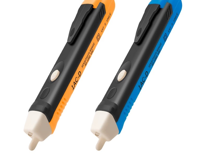
Procurement teams must differentiate between general safety ratings and specialized high-voltage standards. A standard pen tester usually carries a CAT III or CAT IV rating. This qualifies it for building wiring, breaker panels, and low-voltage utility drops. It does not qualify it for transmission lines.
Grid-level high-voltage work requires tools certified under specific ASTM or IEC standards. You must enforce a strict rule across your organization: A CAT IV 1000V non-contact pen is never a substitute for an ASTM-rated high-voltage utility detector.
Standard Type | Typical Application | Testing Mechanism | Regulatory Examples |
CAT III / CAT IV | Commercial building wiring, low-voltage panels. | Low-voltage capacitive coupling (up to 1000V). | UL 61010-1, EN 61010-1 |
High-Voltage Standards | Utility grid infrastructure, substations. | Direct physical contact or specialized high-field sensing. | ASTM F1796, IEC 61243-1 |
Physical Design and Ergonomics
Look closely at probe geometry before purchasing. Manufacturers design modern tamper-resistant receptacles with tight internal shutters. If the tester tip is too thick, it cannot penetrate the slot. Evaluate tip thickness carefully to ensure broad compatibility across residential and commercial sites.
You must also assess capability for back-wired switches. Contact probes often cannot reach deep recessed terminals. A well-designed non-contact tip can press flat against the switch housing to sense the field safely.
UI and Diagnostic Clarity
Clear alert mechanisms prevent fatal misinterpretation. Evaluate how the device differentiates between standby lights, low-battery indicators, and active voltage alarms. If the standby blinking light matches the color of the active alert, workers will eventually make a mistake.
Always demand built-in self-test functionality. The tool should internally verify battery health and circuit integrity before every use. If the internal circuit fails, the device should refuse to turn on. This prevents a worker from trusting a broken tool.
Integration Strategy: Building a Fail-Safe Testing Protocol
Why Professional Toolkits Require Both
You cannot rely on a single instrument for comprehensive electrical safety. Professional toolkits require both technologies working in tandem. Frame the non-contact tool as the preliminary scout. It surveys the area, maps the landscape, and identifies immediate hazards. Frame the contact tester as the final judge. It issues the final verdict before anyone touches bare copper.
The "Live-Dead-Live" SOP
You must integrate a strict verification sequence into your safety manual. We call this the "Live-Dead-Live" Standard Operating Procedure. It applies directly to final isolation tasks.
Step 1: Test the voltage detector on a known live source. Confirm the instrument functions perfectly.
Step 2: Test the target circuit to ensure it is completely de-energized. Look for absolute zero.
Step 3: Re-test on the known live source. This verifies the tool did not malfunction or lose battery power during Step 2.
Shortlisting Logic for Buyers
Procurement teams need a clear decision framework. Choose non-contact tools featuring adjustable sensitivity. A dual-range detector helps frontline workers distinguish between high-voltage lines and low-voltage control circuits. Mandate robust self-test features for any frontline tool.
For final safety verification, mandate strict adherence to dedicated two-pole contact testers. They ensure total compliance with Lockout/Tagout (LOTO) requirements.
Tool Category | Primary Role | Ideal Features to Shortlist |
Non-Contact Detector | Preliminary scouting and rapid triage. | Dual-range sensitivity, built-in self-test, distinct audible/visual alarms. |
Contact Tester | Final verification and LOTO compliance. | Single-function interface, rugged probes, ghost-voltage immunity. |
Conclusion
A non-contact device offers unmatched speed during facility inspections. It provides specialized safety benefits, such as identifying lethal open-neutral situations. However, it inherently lacks the physical verification power of a contact tester. You cannot use an indicator to prove a circuit is definitively dead.
Invest in Both: Equip your team with high-quality, CAT-rated models of both technologies. They complement each other perfectly.
Update Manuals: Explicitly define acceptable use-cases for each tool in your company safety manuals. Eliminate field guesswork immediately.
Enforce Live-Dead-Live: Make the Prove-Test-Prove methodology mandatory for any physical isolation task.
Respect Limits: Train technicians to understand the severe limitations of capacitive coupling, especially regarding shielded cables and wet environments.
FAQ
Q: Can a non-contact voltage detector measure DC voltage?
A: No. These devices rely entirely on capacitive coupling. This physical process requires a fluctuating, alternating electric field to trigger the internal sensor. Direct Current (DC) generates a static field, which the sensor cannot detect. You must use a contact multimeter for solar, automotive, or battery systems.
Q: Why is my voltage detector beeping when the power is off?
A: You are likely experiencing "ghost voltage." Parallel live cables running close to your dead wire can induce a sympathetic electric field. Environmental interference from heavy machinery or nearby Wi-Fi routers can also trigger the sensitive antenna. This represents a false positive.
Q: Are non-contact voltage testers safe to use as a primary safety check?
A: They are only safe as a preliminary indicator. They are never safe as a primary verification check. Industry standards dictate you must use a contact tester to prove a circuit is electrically dead before touching bare metal.
Q: How often should I test my voltage detector?
A: You must test the device every single time you intend to use it. You should perform the "Live-Dead-Live" verification. Test it on a known live source before checking your target circuit, and test it again immediately after to confirm it did not break during use.


