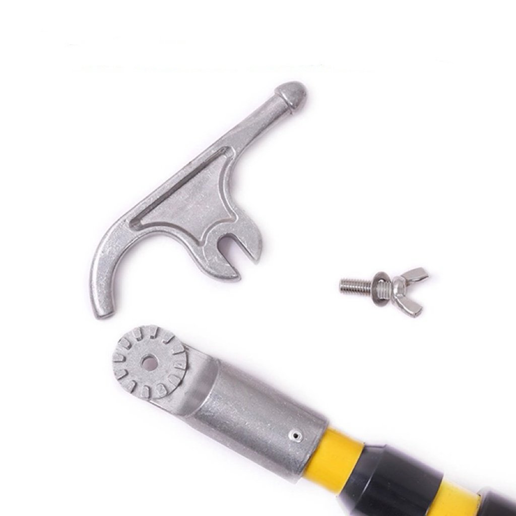
Live-line power distribution work leaves zero margin for error. Mechanical failure, structural deflection, or electrical tracking along insulating opearting rods can result in catastrophic phase-to-phase or phase-to-ground faults. Utility crews operate in environments where dynamic tension, unpredictable weather, and high voltages intersect constantly. Under these conditions, the structural and dielectric integrity of your tools is the only barrier between routine maintenance and a fatal incident.
Utility procurement teams, fleet engineers, and safety managers struggle to balance mechanical load-bearing limits (WLL) with verified dielectric insulation ratings when matching Link Sticks to specific field tasks like conductor lifting, tensioning, and dead-end maintenance. Selecting the wrong tool or underestimating dynamic line tension compromises crew safety and grid reliability.
This guide serves as a technical, field-focused framework for evaluating, comparing, and selecting high-performance link sticks and insulating operating rods based on advanced material design, mechanical safety margins, and strict ASTM/OSHA compliance.
Selection must prioritize verified dielectric strength (ASTM F711 compliance) alongside specific working load limits (WLL) calculated with dynamic safety margins (typically 3:1 or 5:1).
Different applications require distinct mechanical designs; strain, roller, suspension, and spiral link sticks feature unique loading characteristics and are not structurally interchangeable.
The integrity of insulating operating rods depends heavily on material composition—specifically, void-free, unicellular polyurethane foam-filled fiberglass-reinforced plastic (FRP).
Environmental variables like humidity and rain require specialized design features, such as silicone water-shedding skirts (deflectors), to prevent surface tracking.
Comprehensive field lifecycle management must combine daily pre-use portable dielectric testing with biennial laboratory testing mandated by IEEE Std 978 and OSHA regulations.
Defining Success Criteria for Link Sticks in Distribution Work
Operational Baselines and Safety Margins
Link sticks serve a dual function in distribution work. They provide absolute electrical isolation while bearing significant, highly variable mechanical loads. A tool must perform both functions flawlessly under stress. If the insulation fails, current tracks directly to the operator. If the mechanical structure fails, conductors drop, creating immediate arc flash and physical hazards for the crew below.
Success criteria begin with establishing minimum approach distances (MAD) based on phase-to-phase voltage classifications. The tool must provide adequate electrical clearance and prevent clearance path bridging. Mechanically, the baseline is zero structural deformation or fiber delamination under peak dynamic tension. You must account for unexpected wind loads, ice accumulation, and line-snap rebounds during tensioning operations. A static load calculation is never enough in the field.
Standard Minimum Approach Distances (MAD) Reference
Voltage Range (Phase-to-Phase)
Minimum Approach Distance (AC)
Primary Tool Requirement
50 V to 300 V
Avoid Contact
Insulated Hand Tools
301 V to 750 V
1 ft. 0.9 in. (0.33 m)
Low-Voltage Sticks
751 V to 15 kV
2 ft. 1.4 in. (0.65 m)
Standard Link Sticks
15.1 kV to 36 kV
2 ft. 7.2 in. (0.77 m)
Extended Link Sticks
36.1 kV to 46 kV
2 ft. 9.2 in. (0.84 m)
Heavy-Duty Link Sticks
Regulatory and Compliance Frameworks
OSHA 1910.269 regulations dictate mandatory compliance lenses for live-line tool inspection, electrical testing, and field maintenance. These rules establish strict protocols for removing damaged tools from service. They also mandate regular testing cycles to verify dielectric integrity before tools return to the fleet.
Manufacturing standards are equally strict. ASTM F711 specifications govern the production of fiberglass-reinforced plastic (FRP) rods and tubes used in live-line tools. This standard ensures the rods contain no voids, inclusions, or manufacturing defects that could compromise insulation. Furthermore, IEEE Std 978 guidelines address in-service maintenance and electrical testing. This establishes testing intervals and voltage thresholds, typically requiring 75 kV AC per foot for in-service testing.
Solution Categories: Types of Link Sticks and Their Applications
Strain Link Sticks
Strain link sticks support high linear tension loads. Crews use them extensively during conductor repairs, dead-end insulator replacements, splicing, or line cutting. These tools feature heavy-duty, heat-treated steel or structural aluminum alloy end fittings. You will typically see clevises, eyes, or adjustable hooks. Manufacturers epoxy and pin these fittings directly to the FRP rod for maximum pull strength.
You must understand their critical limits. Strain sticks are engineered exclusively for linear tension. They are highly susceptible to catastrophic shear failure if subjected to bending moments or cantilever loads. Misaligning a strain stick during a heavy pull can snap the rod instantly, dropping the line.
Roller Link Sticks
Roller link sticks spread, position, and hold energized conductors aside during pole replacement or maintenance. They allow longitudinal conductor movement, which is essential when pulling slack. The design incorporates non-conductive, heavy-duty polymer rollers or bronze-bushed metallic rollers mounted to an insulated fork.
These tools have considerably lower mechanical Working Load Limits (WLL) compared to strain link sticks. The roller bearings require continuous monitoring in the field. Friction-induced heating or bearing seizure can damage the conductor jacket or compromise the tool's structural integrity over time.
Suspension Link Sticks
Suspension link sticks handle vertical support tasks. Crews use them to lift and hold conductors during crossarm replacements or insulator assembly changes. They are often deployed in tandem with auxiliary crossarms, gin poles, or wire tongs. They are engineered for pure vertical load-bearing capacity and often feature quick-change adapter heads or specialized hook designs for secure conductor engagement.
These sticks are susceptible to lateral wind-load deflection. You must size them correctly by rod diameter to prevent dangerous bowing under heavy vertical loads combined with crosswinds. A bowing stick is a failing stick.
Spiral Link Sticks
Spiral link sticks provide temporary separation, positioning, or quick capture of conductors. They are ideal for situations where manual locking pins are impractical or too slow to deploy. The design features a corkscrew or spiral-configured hook that engages the conductor with a simple twisting motion.
These are strictly for light-duty applications. They are not rated for high mechanical tension or heavy conductor lifting. Using a spiral stick for load-bearing tasks risks immediate failure and severe safety violations.
Technical Evaluation Dimensions for Insulating Operating Rods
Material Science: Core and Surface Coatings
Hollow rods are entirely unsuitable for load-bearing link sticks because internal moisture condensation creates a conductive path. High-quality sticks utilize closed-cell, unicellular polyurethane foam inside the fiberglass tube to completely block moisture migration. This foam core ensures the internal dielectric strength remains intact regardless of external humidity or temperature swings.
The resin and fiber architecture dictates mechanical strength. High-density, continuous-strand fiberglass filaments bound with specialized epoxy resin resist mechanical crushing and longitudinal splitting. The surface finish must be smooth, high-gloss, and hydrophobic. Polyurethane or specialized epoxy coatings prevent dust accumulation, oil absorption, and subsequent electrical tracking along the shaft.
Wet-Weather Performance and Surface Tracking Mitigation
Humidity, rain, and airborne contaminants drastically reduce the surface dielectric strength of insulating operating rods. A continuous film of water acts as a conductor, allowing current to track down the stick directly to the operator's hands.
To mitigate this, manufacturers install silicone water-shedding skirts, or deflectors, along the link stick. These skirts break up continuous water films, converting a potential tracking path into discrete, non-conductive droplets. This feature is essential for maintaining safety margins in wet, coastal, or foggy environments.
Mechanical Sizing and Load Factor Math
Selecting the correct rod diameter is necessary for managing deflection. Standard nominal rod diameters include 1-1/4", 1-1/2", 2", and 2-1/2". Thicker rods offer higher load capacities and reduced bowing but increase tool weight and operator fatigue. You have to balance strength with usability.
Determine the absolute maximum static load of the conductor segment.
Apply dynamic multipliers for wind, ice, and rigging angles.
Calculate the required Ultimate Breaking Strength using a minimum 3:1 safety factor.
Select a rod diameter that minimizes deflection under the calculated Working Load Limit (WLL).
Verify the end fittings match the required WLL of the fiberglass rod.
Understanding the safety factor equation is mandatory. You must differentiate between Ultimate Breaking Strength and the Safe Working Load Limit (WLL). A 3:1 safety factor is the minimum baseline for standard operations. However, a 5:1 factor is preferred for critical dynamic line-lifting procedures to account for unexpected shock loads. Link sticks are also vulnerable to torsional twist and off-axis loads during installation rigging, which must be factored into load calculations.
Hardware Interface and Mechanical Fail-Safes
The physical connection between the FRP rod and metal end fittings is a common failure point. Look for interference-fit, pinned, and epoxied assemblies designed to distribute tensile stresses evenly without causing fiber crush at the joint.
Some manufacturers integrate mechanical fail-safes, such as calibrated sacrificial shear pins. These pins are designed to break before the FRP rod fails structurally, preventing catastrophic conductor drops if structural limits are exceeded. This provides a controlled failure mode rather than an explosive structural collapse.
Cost vs. Value: Conceptual Trade-offs in Procurement
Upfront Capital Expense vs. Operational Lifecycle Durability
Procurement often weighs low-cost utility rods against premium link sticks. Premium tools utilize UV-stabilized resins and enhanced hydrophobic coatings. These advanced materials delay yellowing, fiber blooming, and premature field retirement. While the initial capital expense is higher, the operational lifecycle durability significantly reduces long-term replacement costs.
Cheaper fiberglass formulations degrade faster under UV exposure. This degradation increases the operational cost through frequent laboratory refinishing, recoating, and testing cycles. Investing in premium materials reduces downtime and maintenance overhead for the entire fleet.
Comparison of Standard vs. Premium Link Stick Materials
Feature
Standard Utility Grade
Premium Grade
Resin Type
Basic Polyester
UV-Stabilized Epoxy
Core Material
Standard Foam
Unicellular Polyurethane
Surface Finish
Standard Gloss
Hydrophobic Polyurethane
Expected Lifespan
3-5 Years
7-10+ Years
Fleet Standardization vs. Task-Specific Optimization
Standardizing a fleet on a limited range of highly versatile, heavy-duty adjustable strain and suspension link sticks simplifies crew training, storage, and annual testing logistics. This approach improves operational efficiency and reduces inventory complexity across multiple utility trucks.
However, over-standardization carries risks. Crews might use a sub-optimal tool, such as deploying a heavy strain stick as a light-duty positioning tool. This increases physical fatigue and lowers precision in tight workspaces. A balanced approach provides standard heavy-duty tools alongside necessary task-specific options for specialized rigging.
Field Implementation Risks and Technical Mitigation Strategies
Surface Degradation and Physical Damage
Physical abrasions, gouges, or impact fractures expose raw glass fibers, a condition known as fiber blooming. This creates capillary pathways for moisture and carbon tracking, destroying the tool's dielectric properties instantly.
Mitigate this risk by mandating daily visual and tactile inspections. Crews must perform "wipe-and-feel" tests to detect microscopic surface cracking. Establish clear pass/fail thresholds distinguishing superficial scratches from deep structural gouges requiring immediate removal from service.
Environmental Degradation and Inadequate Field Testing
Visual inspection has severe limitations. Internal foam contamination or microscopic moisture ingress cannot be detected by the naked eye. Relying solely on visual checks leaves crews vulnerable to hidden dielectric failures during live-line work.
Implement mandatory pre-use electrical testing. Crews must use portable high-frequency dielectric testers, commonly known as hot stick testers, prior to deploying any insulating operating rods on energized conductors. This verifies insulation integrity immediately before use.
Improper Storage and Transportation Realities
Link sticks sliding freely in utility trucks suffer severe mechanical and chemical exposure. They are battered by other tools and exposed to fuel vapors, hydraulic fluids, and road salt, all of which degrade the fiberglass resin rapidly.
Enforce strict storage protocols. Mandate the use of dedicated, weather-tight PVC storage tubes, heavy-duty protective canvas wraps, or custom padded carrying bags on all utility and bucket trucks. Proper storage drastically extends tool lifespan and maintains dielectric integrity.
Dynamic Overloading and Miscalculated Line Tension
Static tension calculations are often insufficient. Dynamic wind loading, ice accumulation, or unequal pulling speeds during tensioning can easily double the static tension on a link stick, pushing it past its WLL.
Integrate dynamic variables into pre-job tension calculations during crew briefings. Mandate the use of inline mechanical or digital dynamometers when rigging unknown conductor loads to ensure tension remains within safe operating limits at all times.
Conclusion
Selecting the right link sticks requires aligning the physical mechanical limits of the tool with certified dielectric safety clearances under wet, dynamic field conditions. Prioritize ASTM F711 compliance and calculate required WLL using a minimum 3:1 safety factor. Evaluate environmental extras like silicone water-shedding skirts based on your regional climate.
Conduct an immediate safety audit of current live-line tool inventories for signs of fiber blooming or outdated testing stamps.
Incorporate portable, high-frequency dielectric testing devices into all standard line truck tool complements.
Request certified dielectric and tensile destructive test reports from prospective manufacturers before finalizing high-volume procurement contracts.
Implement mandatory dynamometer usage for all unknown conductor tensioning tasks.
FAQ
Q: How often should link sticks undergo laboratory testing?
A: According to IEEE Std 978 and OSHA regulations, live-line tools must undergo formal laboratory dielectric testing at least every two years. Test them more frequently if field inspections reveal damage or if the tool has been subjected to severe electrical or mechanical stress.
Q: Can I use a strain link stick for vertical lifting?
A: No. Strain link sticks are engineered specifically for linear tension loads. Using them for vertical lifting introduces bending moments and cantilever loads that can cause catastrophic shear failure. Always use suspension link sticks for vertical lifting tasks.
Q: What is fiber blooming and why is it dangerous?
A: Fiber blooming occurs when physical damage or UV degradation exposes the raw fiberglass strands beneath the resin coating. Exposed fibers absorb moisture and dirt, creating a conductive pathway that destroys the tool's dielectric insulation, risking electrical tracking.
Q: Why do some link sticks have silicone skirts?
A: Silicone water-shedding skirts, or deflectors, break up continuous films of water on the rod's surface during rain or high humidity. By converting the water into discrete droplets, the skirts prevent electrical current from tracking down the wet surface to the operator.
Q: What is the difference between Ultimate Breaking Strength and Working Load Limit (WLL)?
A: Ultimate Breaking Strength is the absolute maximum load a tool can withstand before catastrophic structural failure. The Working Load Limit (WLL) is the maximum safe load for regular operation, calculated by dividing the breaking strength by a safety factor to account for dynamic stresses.
Q: How do I properly store link sticks on a utility truck?
A: Store link sticks in dedicated, weather-tight PVC storage tubes, heavy-duty protective canvas wraps, or custom padded carrying bags. Never leave them loose in a truck bed where they can be damaged by other tools, chemicals, or road debris.